

Rigid-Flex Printed Circuit Board
A rigid-flex printed circuit board is a combination of rigid and flexible materials bonded together. The flexible sections allow the board to bend and fold. A rigid section supports the flexed sections and provides mechanical stability. This type of PCB is designed for use in industrial and automotive applications where electronics may be subjected to vibration, shock, and heat. It is also ideal for consumer electronic products because it reduces the size of the device and enhances durability.
The process of making a rigid-flex printed circuit board begins with the creation of an accurate electrical layout. The design is etched onto the copper layers using imaging and etching processes, which create reliable electrical pathways. A layer of epoxy or polyimide serves as a protective coverlay.
Once the design is established, it must be cut to the appropriate dimensions and shapes. Cutting can be done by a variety of methods, including routing, laser cutting, and mechanical sawing. The precise cuts are needed to ensure that the finished product fits into its intended space in the final product.
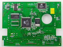
What Materials Are Used in a Rigid-Flex Printed Circuit Board?
Rigid-flex PCBs are often used in electronics that are prone to vibration and shock, especially those designed for the medical industry. These circuits are also able to resist environmental hazards such as high temperatures, radiation, and chemical exposure. They are also useful in automotive applications, where they can be used to improve the performance of infotainment systems and sensors while maintaining the compact size of the vehicle’s interior.
The conductor material of a rigid-flex PCB can be made of a number of different materials, depending on the application. If the flex section will be subjected to a lot of stress and strain, it is recommended that designers choose rolled annealed (RA) copper foil. This material is more springy than normal copper, which allows it to stretch before fatigue cracking occurs. In addition, the RA foil undergoes an annealing process that elongates the copper’s grain structure in a planar direction.
In addition to choosing a suitable conductor material, designers should pay close attention to the way they route traces on the flex section. It is best to have all traces on the flex section placed on the same side of the board and not overlapping. This helps to decrease the amount of stress on the flex section and prevents signal impedance mismatches. It is also advisable to use pad-only plating on the flex section in order to minimize copper thickness and to aid in achieving a high etch yield.
Rigid-flex circuits can be a complex assembly, but they are a great option for many applications. They provide a cost-effective alternative to traditional rigid boards while delivering better reliability and functionality. The key to designing a successful rigid-flex board is to keep the flex section as thin as possible and to use high-quality, reliable materials. Doing this will help to avoid costly manufacturing errors such as test failures, rework and scrapping. It is also important to keep the flex area away from the rigid areas of the board to prevent thermal damage and vibration.